PI offers the largest nanopositioning systems selection
of research- and industrial-reliability Piezo Actuators, Translators (linear
actuators), Piezo Nano Positioning Solutions and Piezo Steering Mirrors (Active
Optics) worldwide. We have more than 30 years experience.
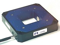
The PI piezoelectrically driven EDM (Electric
Discharge Machining) cut flexure stages offer displacement ranges of 5
to 1800µm (rotation to several mrad) and limit out plane motion to
sub-nm/sub-arcsecond deviation/tilt.
Why Flexures?
Flexure motion is based on the elastic deformation (flexing) of a solid material. Friction and stiction are entirely eliminated, and flexures exhibit high stiffness, load capacity and resistance to shock and vibration. Flexures are maintenance free and not subject to wear. They are vacuum compatible, operate over a wide temperature range and require neither lubricants nor compressed air for operation.
Travel Ranges
The latest flexure guided nanopositioning stages provide travel ranges close to 2 mm (see P-629 PIHera® stages). For longer travel ranges, the novel
NEXLINE® and NEXACT® nanopositioning motors are available. These motors were developed to overcome the limitations of nanopositioning devices in the semiconductor industry. For more information see Semi TIS Award presentation .
Anti-Runout Multilink Flexures: Excellent Guiding Accuracy
The multilink flexure guiding systems employed in most PI piezo nanopositioners (Fig. ) eliminate cosine errors and provide bidirectional flatness and straightness in the nanometer or microradian range. This high precision means that even the most demanding positioning tasks can be run bidirectionally for higher throughput.
Most of the our flexure stages can
be fitted with our low cost piezoresistive sensorrs or high-end capacitive sensors which provide resolution and repeatability
better than 1 nm.
Features of the PI flexure stages include:
-
Single and multi-axis systems up to 6 degrees
of freedom.
-
Single Module Parallel-Kinematic multi-axis
systems with large aperture.
-
Ultra-fast response
-
Advanced Control Techniques for fastest possible
settling
-
Optional integrated position feedback for
closed loop operation and non-linearity compensation.
-
Step or continuous operation: step response
in low millisecond range.
-
Optional integrated capacitive displacement
sensors with <1 nm accuracy.
-
OEM and custom designs.
Read the Nanopositioning BLOG
|
Parallel and Serial Flexure Designs
 There are two ways to achieve multi-axis motion: parallel and serial kinematics. Serial kinematics (nested or stacked systems) are simpler and less costly to implement, but they have some limitations compared to parallel kinematics systems .
Serial Kinematics Flexures for Lower Cost / Standard Applications
In a multi-axis serial kinematics flexure system, each actuator & position sensor controls one DoF. Serial kinematic flexure designs have advantages when it comes to cost and simplicity, and work very well for most standard applications.
No Crosstalk?
However, the manufacturing precision of even the best machines (and technicians) does not allow for completely crosstalk-free mechanics, at least not at the nanometer level, even in quasistatic operation. For many applications this is not a limitation. In a parallel kinematics multi-axis flexure system, all actuators act directly on the same moving platform (relative to ground), enabling reduced size & inertia, and the elimination of microfriction caused by moving cables . Identical resonant frequency and symmetrical dynamic behavior can be obtained for both the X & Y axes. Advantages are higher dynamics and scanning rates, better trajectory guidance as well as better reproducibility and stability. However, without the proper test metrology / instrumentation these advantages can easily be overlooked, because they are not apparent at the micrometer level, or when the internal stage sensor system is used as the reference system. In this case a serial kinematics system may appear to be perfect and designer not experienced in the nanoworld, could be tempted to draw the conclusion there is no cross talk (see also "Coupled and Uncoupled Motion..." below).
Parallel Kinematics for Highest Multi-Axis Precision / Dynamics.
For the ultimate in dynamics straightness/flatness/orthogonality and for coordinate transformation situations (such as rotating about an arbitrary point in space), parallel kinematics is required. Parallel Kinematics systems, if designed well, are superior to serial kinematics systems. A comparison that comes to mind is the electronic computer and the slide ruler. Both can be used to solve many problems, but a computer can do more, faster. To reap the benefits of parallel kinematics, you must have high-bandwidth, direct drivetrain-output metrology, so the workpiece can be simultaneously observed and controlled in multiple degrees of freedom.
Because it takes more knowledge, experience and more advanced controllers to produce a good parallel kinematics precision positioning system, inexperienced designers may avoid that challenge dismissing the technology as unpredictable, uncontrollable. Everyone who has seen a modern hexapod 6-axis motion system compared to a classical stack of translation and rotation stages will immediately understand the benefits of parallel kinematics.
Coupled and Uncoupled Motion, Static and Dynamic
Serial kinematics are sometimes referred to as uncoupled motion systems vs. coupled motion systems for parallel kinematics. When it comes the nanometer realm, there is no uncoupled motion. By nesting or stacking a second and/or third axis onto a translation stage, there will be an influence on the first axis. Any load attached will have a further influence on all axes, even when at rest. Since we are talking about positioning, things are not always at rest, actually most nanopositioning / scanning applications require very high dynamics. The seemingly uncoupled multiaxis-system then provides coupled (unwanted) motion in many degrees of freedom, that cannot be detected by its internal serial metrology sensors and hence goes partially uncontrolled. These errors may not be critical in many applications, but can be detrimental in some others.
|